Leave Your Message
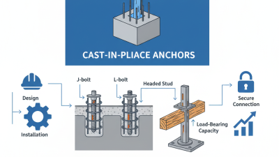
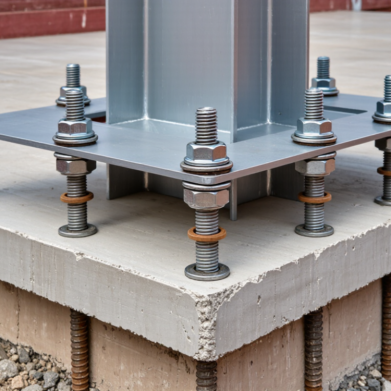
Anchoring Bolts In Concrete Foundations connect a structure’s base to the concrete below it. They help resist forces that could shift, lift, or overturn columns, equipment, and frame supports. A steel column may look firmly seated, yet wind, vibration, or an uneven load can place real stress on its connection. Bolts provide a defined load path from the supported structure into the foundation.
The details matter. Bolt diameter, embedment depth, spacing, concrete strength, and edge distance all affect performance. So does installation: a bolt set slightly out of position can complicate base-plate fitting, while poor anchorage may reduce the connection’s capacity. Small errors count. Designers select anchoring systems for the expected loads and site conditions, then rely on approved drawings and product guidance for placement and inspection. Actual requirements vary by project; no single bolt arrangement suits every foundation.
This guide explains why these bolts are used, how they transfer forces, and which factors shape their selection. It also considers common installation concerns, including alignment and concrete placement. A practical point can be easy to miss: the bolt alone does not make a connection safe. The plate, welds, concrete, and surrounding reinforcement matter too. That deserves a second look. Understanding these parts helps owners and builders ask better questions and recognize when project-specific engineering advice is needed.
Why Are Anchoring Bolts Used in Concrete Foundations?
Identify the Loads: Tension, Shear, and ACI 318 Anchor Design
Anchoring bolts connect a foundation to columns, equipment, and structural frames. Their job is not simply to hold parts in place. They transfer tension from uplift, shear from lateral movement, and sometimes both at once. Picture a steel column base: wind can push it sideways while overturning forces pull one edge upward. Small details matter.
ACI 318-19 Chapter 17 requires designers to check several possible failure modes, including anchor steel failure, concrete breakout, pullout, and pryout. For combined tension and shear, Section 17.8 applies an interaction check when either demand exceeds 20 percent of its design strength. When both exceed that threshold, their normalized demands must generally total no more than 1.2. ACI 355.2-22 also sets qualification tests for post-installed anchors, including performance in cracked concrete. These are design checks, not substitutes for project-specific calculations.
In practice, edge distance, embedment depth, spacing, and concrete condition can change capacity substantially. A bolt close to a slab edge may trigger concrete breakout before the steel yields. Installation matters, too: debris in a drilled hole can undermine an otherwise sound detail. Drawings may look clear, yet field tolerances still deserve attention. The adopted code edition and actual site conditions should guide final design.
| Design Item | What It Means | Typical Source or Example | Key Design Considerations | ACI 318 Design Focus |
|---|---|---|---|---|
| Purpose of anchoring bolts | Connect a structural element or base plate to a concrete foundation and transfer forces across the connection. | Steel column, equipment skid, sign support, or other base-mounted structure. | Coordinate bolt layout, base-plate holes, installation tolerances, grout, and foundation reinforcement. | Design the anchor-to-concrete connection for the applicable factored forces and failure modes. |
| Tension | Force that pulls an anchor away from the concrete, along the anchor’s axis. | Wind uplift, overturning of a column or support, or equipment uplift. | Check anchor steel strength and relevant concrete failure modes. Anchor group behavior and load distribution may affect demand. | Chapter 17 includes checks such as steel strength, concrete breakout, and pullout, as applicable to the anchor type and conditions. |
| Shear | Force acting parallel to the concrete surface and across the anchor connection. | Wind or seismic forces, lateral equipment loads, or a supported member’s horizontal reaction. | Consider anchor steel strength, concrete edge distance, spacing, and whether a shear lug or other load-transfer detail is used. | Chapter 17 includes checks such as steel strength, concrete breakout at an edge, and pryout, where applicable. |
| Combined tension and shear | Concurrent axial pull and lateral force on the anchor or anchor group. | Overturning systems that produce uplift while also resisting horizontal forces. | Evaluate the governing load combinations and the code-prescribed interaction of tension and shear strengths. | Apply the applicable Chapter 17 interaction provisions after determining the relevant design strengths. |
| Concrete breakout | A cone- or edge-related portion of concrete separates around an anchor or anchor group. | Anchors with limited embedment, close spacing, or small distances to a free edge. | Embedment depth, edge distance, anchor spacing, group geometry, cracking, and reinforcement can influence strength. | Determine breakout strength using the applicable Chapter 17 provisions and project-specific concrete properties and geometry. |
| Pullout and bond-related behavior | The anchor pulls out of the concrete or loses load transfer through its anchorage mechanism. | Cast-in headed anchors or post-installed anchors, depending on anchor type and installation. | Use the correct design provisions for the anchor product and installation; do not assume different anchor types behave alike. | Check the applicable pullout or bond-related provisions and any required qualification or evaluation criteria. |
| Cracked concrete | Concrete in the anchorage region may be cracked under service or design conditions. | Common structural regions subject to flexure, restraint, or load reversals. | Establish whether cracked-concrete design is required and verify that the selected anchor is qualified for the intended condition. | Use the relevant cracked-concrete provisions and anchor qualifications required by the governing code and project documents. |
| Embedment, spacing, and edge distance | Geometric dimensions that influence anchor capacity and the size of concrete failure regions. | Anchor placement within a base plate and foundation, including proximity to foundation edges. | Check actual installed geometry, group effects, reinforcement conflicts, and construction tolerances. | Use Chapter 17 equations and limits for the actual anchor arrangement; there is no universal spacing or embedment for every design. |
| Load path and reinforcement | The complete route by which forces pass from the supported element through the anchors and into the foundation. | Base plate, anchor rods, grout, foundation concrete, and foundation reinforcement. | Confirm that the foundation and its reinforcement can carry the transferred forces; detail reinforcement where required by the design. | Check anchor design together with applicable concrete member, reinforcement, and load-combination requirements. |
| Design information required | Project-specific inputs used to calculate anchor demands and strengths. | Factored tension and shear, concrete strength, anchor type and size, embedment, spacing, edge distances, and seismic or cracked-concrete conditions. | Use verified drawings, material properties, installation requirements, and the adopted building-code edition. | ACI 318 Chapter 17 provides anchor design provisions; final design must follow the adopted edition and applicable project requirements. |
Note: This table summarizes common design considerations; it is not a substitute for project-specific calculations. Anchor capacity depends on the anchor system, concrete condition, geometry, applied loads, installation, and governing code requirements.