Leave Your Message
Choosing among China’s leading buffer stopper manufacturers takes more than comparing catalog prices. The right supplier should explain how its Buffer Stop Buffer Stopper Bf is designed for the stated load, impact speed, travel distance, and installation conditions. Ask for material specifications, test records, drawings, and clear guidance on inspection and maintenance. A well-finished unit, consistent welds, and traceable components matter. So does a supplier’s willingness to discuss limitations.
This guide compares ten manufacturers through practical purchasing questions: product range, engineering support, customization, quality controls, delivery capability, and after-sales service. It is an introduction, not a substitute for a project-specific engineering review. Small differences in operating conditions can change what counts as a suitable buffer stop. Be careful with broad performance claims; request supporting evidence and confirm that documents match the product being quoted.
A named expert quotation should be checked against a reliable, attributable source. No verified quotation from a buffer-stop specialist was supplied for this article, so inventing one would weaken its credibility. That gap deserves attention. Before shortlisting a manufacturer, ask who reviewed the design, what test method was used, and whether the results apply to your application. The answers can reveal more than a polished brochure.
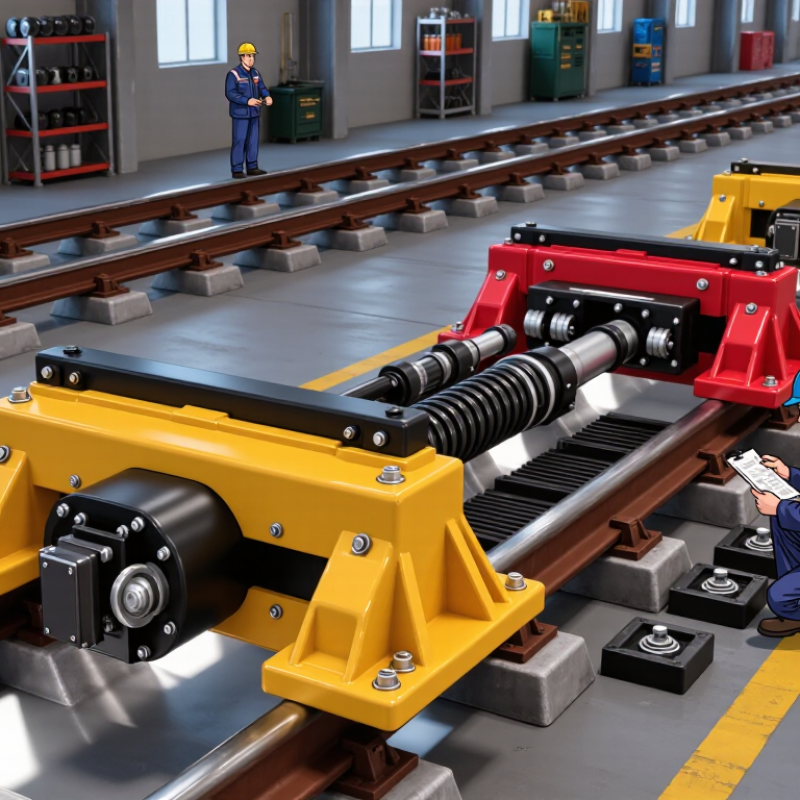
A BF buffer stopper absorbs impact when moving equipment reaches the end of its travel. It helps reduce peak forces and limits damage to frames, rails, or nearby components. The stopper may use an elastomer block, polyurethane, or a spring-and-damper assembly, often supported by a steel housing. Material choice affects stiffness, rebound, wear, and performance across temperature changes. Fit matters. A stopper that is too soft may bottom out; one that is too stiff can transmit sharp loads into its mounting structure.
A load–deflection curve shows how force changes as the stopper compresses. A gradual rise usually indicates progressive resistance, while a steep rise near the end signals increasing stiffness. Engineers compare curves at specified speeds, temperatures, and compression limits, since test conditions can change the result. Not always. A tidy curve does not reveal every service problem: repeated impacts, poor alignment, or aging may alter real-world behavior. Check the mounting surface and available stroke, then compare test data with the expected impact energy. Leave a practical margin. No single curve fits every installation, so field observations should inform later selection and maintenance.
The table below summarizes ten common buffer-stopper design and material configurations. These are general engineering categories, not manufacturer-specific products. Material hardness and load–deflection behavior vary with compound, dimensions, shape, temperature, loading rate, and test method.
| No. | General Configuration | Common Material | Typical Material Characteristics | Typical Load–Deflection Behavior | Common Function or Use |
|---|---|---|---|---|---|
| 1 | Solid cylindrical stopper | Natural rubber (NR) | Commonly compounded across a broad hardness range; resilient with good energy return. | Generally nonlinear; stiffness rises as compression increases. | General-purpose impact cushioning and end-stop protection. |
| 2 | Flanged rubber stopper | NR or styrene-butadiene rubber (SBR) | Elastic rubber compound; flange provides a broader mounting or bearing surface. | Progressive response; flange and mounting conditions affect measured stiffness. | Equipment stops where secure attachment and impact absorption are required. |
| 3 | Conical or tapered stopper | NR or SBR | Tapered geometry changes the contact area as compression increases. | Often progressive, with increasing resistance at higher deflection. | Applications needing a softer initial response and increasing end-of-travel resistance. |
| 4 | Hollow or cup-shaped stopper | NR or SBR | The cavity allows the walls to flex; wall thickness and cavity geometry strongly affect stiffness. | Typically softer at initial compression, becoming stiffer as the cavity closes or walls engage. | Light-to-moderate impact cushioning where additional deflection is useful. |
| 5 | Oil-resistant stopper | Nitrile rubber (NBR) | Selected where resistance to oils and fuels is needed; compatibility depends on the specific fluid and compound. | Rubber-like nonlinear response; geometry and formulation determine stiffness. | Stops near machinery or equipment exposed to compatible oils or petroleum-based fluids. |
| 6 | Weather-resistant stopper | EPDM rubber | Commonly chosen for resistance to weathering, ozone, and water; generally unsuitable for petroleum oils. | Nonlinear elastomer response; temperature and compound influence the curve. | Outdoor equipment and applications exposed to rain, sunlight, or ozone. |
| 7 | Low-temperature stopper | Silicone rubber or a specified low-temperature rubber compound | Compound selection is important because elastomer flexibility changes with temperature. | Curve can shift with temperature; verify performance at the service temperature. | Equipment operating in cold environments, subject to compound-specific limits. |
| 8 | High-abrasion stopper | Polyurethane elastomer (PU) | Often selected for abrasion and wear resistance; properties vary substantially by formulation. | Can provide a firm, progressive response; test data are needed for design loads. | Repeated-contact applications where wear resistance is a priority. |
| 9 | Rubber-to-metal bonded stopper | Rubber bonded to a steel or other metal insert | The insert supports fastening; bond quality and rubber geometry are critical design factors. | Combined response depends on the elastomer, insert, bond, and mounting conditions. | Fixed stops requiring a durable attachment to a machine or frame. |
| 10 | Layered or multi-stage stopper | Rubber layers, or rubber combined with metal components | Layer arrangement and interfaces can be designed to change the response through the compression stroke. | May show staged or progressive stiffness; verify with a representative compression test. | Applications needing a tailored force response over more than one deflection stage. |
Engineering note: A load–deflection curve plots compressive force against deformation. Use test results for the exact stopper geometry, material compound, temperature, and loading conditions when selecting a stopper for a specified load or allowable deflection.