Choosing the right Bolted Fixing Clips begins with understanding the joint, not simply selecting the strongest-looking clip. Each application has different loads, surfaces, access limitations, and maintenance risks. A clip securing cable trays may face vibration, while one holding cladding may experience wind pressure and thermal movement.
John H. Bickford, a widely cited bolted-joint specialist, emphasized this practical principle: “The bolt is not the joint; the joint is the system.” His point remains valuable. The clip, bolt, washer, substrate, and tightening method must work together. A stainless steel clip may resist corrosion, yet it can still fail when installed against a softer material. A heavy-duty clip may appear safer, but its size could prevent proper access or create unwanted stress.
Look closely at the installation environment. Is the surface concrete, steel, timber, or a thin panel? Will moisture collect around the fastener? Could vibration loosen the connection? Check thread engagement, hole diameter, edge distance, and the manufacturer’s torque guidance. Small details matter.
Do not trust appearance alone.
Real projects are rarely perfect. Drawings may omit clearance problems, and installers may use available hardware under pressure. That assumption can fail. A reliable choice balances load capacity, corrosion resistance, fit, installation speed, and future inspection.
This guide explains how to compare Bolted Fixing Clips with greater confidence. It also highlights common selection mistakes, because even experienced teams occasionally overlook the simplest detail.
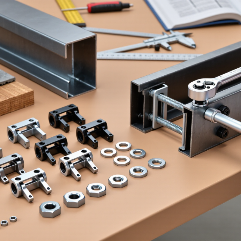
Bolted fixing clips secure pipes, cables, panels, rails, and structural components to a supporting surface. Their purpose is simple: hold parts firmly while managing vibration, movement, and load. A correctly selected clip should not crush the attached component or loosen during service.
Several types serve different needs. U-bolts suit round pipes and tubes, especially when full wrapping support is useful. Saddle clips hold cylindrical parts against a flat surface. Angle clips work well where components meet at a corner or edge. Spring-loaded clips can absorb minor movement, but they may not suit heavy or high-vibration installations. Material also matters. Stainless steel supports corrosion resistance, while coated carbon steel may offer practical strength in sheltered areas. Do not choose by appearance alone.
Tips: Measure the component diameter, bolt hole, and fixing surface before ordering. Check the expected load, vibration, temperature, and moisture. Use compatible washers and nuts, then tighten according to verified technical guidance. Over-tightening can deform thin tubing. Under-tightening may allow rattling. A field inspection should also check rust marks, shifted clips, and damaged surfaces. Small details matter.
In real installations, the supporting substrate is often overlooked. A strong clip cannot compensate for weak concrete, thin sheet metal, or a poorly positioned hole. Review the fixing method against applicable engineering requirements. I would also recheck clearances after installation, because drawings rarely show every practical obstruction. The best choice may not be the most powerful clip, but the one that fits the load, movement, and environment accurately.
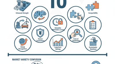
Choosing the right bolted fixing clips starts with the load, not the catalogue photograph. Identify weight, pull-out force, shear, vibration, and impact. A ceiling-mounted cable tray may face steady weight, while machinery adds repeated shock. Calculate the working load per clip, then apply an appropriate safety margin. Do not treat a laboratory maximum as a normal operating capacity. Real installations rarely behave perfectly.
Material selection should match both the clip and the fastener. Stainless steel suits damp areas, but different grades perform differently near salt spray. Coated carbon steel can work indoors when its coating remains intact. Watch for galvanic corrosion when dissimilar metals touch. A thin isolating washer may prevent trouble. Check thread engagement, hole size, washer placement, and tightening torque during installation. Over-tightening can deform the clip. Under-tightening permits movement. Fit matters.
Review temperature, moisture, chemicals, ultraviolet exposure, and dust. A clip near a boiler may lose strength sooner than room-temperature data suggests. Outdoor fittings need drainage and inspection access. I may be cautious, but I would test a sample assembly under representative load. Inspect it after vibration or wet exposure. This can reveal slipping, edge damage, or unexpected corrosion. I have seen sound calculations fail because the supporting surface was weaker than the clip. Verify the substrate, not just the hardware. Document uncertain assumptions and request engineering review before installation.
How to Choose the Right Bolted Fixing Clips?
Matching Clip Dimensions with Bolts and Mounting Surfaces
Choosing a bolted fixing clip starts with accurate measurements, not visual judgment. Check the bolt diameter, thread type, hole clearance, and clip slot width. The clip should hold the bolt without forcing it sideways. Its grip range must also match the mounting surface thickness. A clip designed for a 3 mm panel may loosen on a 1 mm sheet. On thicker material, the bolt may not provide enough thread engagement. Always check the washer diameter and bolt length together. A suitable washer spreads pressure across the clip and reduces local deformation.
Tips: Measure the surface with calipers, then test-fit one clip before ordering more. Leave room for paint, coatings, and minor alignment errors. Check the manufacturer’s load data and tightening guidance when available.
Mounting surface material changes the selection. Steel, aluminum, and composite panels respond differently to clamping force. A sharp-edged clip may mark a coated surface or create corrosion around the hole. Use a protective finish or isolation layer when needed. I once treated a close visual fit as acceptable, but vibration exposed the mistake within weeks. The bolt was correct; the clip grip was not. That small oversight required rework. Field conditions can be less perfect than a drawing. Recheck the assembly after installation, especially where vibration, heat, or repeated movement is expected.
Bolted fixing clips should be chosen by installation method, expected load, and maintenance access. Through-bolting usually provides dependable strength because the bolt passes through the supporting material. It needs rear access, accurate drilling, and suitable washers. Threaded inserts install neatly from one side, but their pull-out strength depends heavily on the base material and embedment depth. Clamp-style clips are faster to fit and useful for temporary adjustments. They can lose grip under vibration if torque is inconsistent.
Strength is not determined by the clip alone. Load direction, bolt grade, hole clearance, edge distance, and substrate condition all matter. A clip fixed to cracked concrete may fail before the metal bends. Use a calibrated torque wrench, then record the setting. Hand-tightening feels efficient, but it creates uneven results. Maintenance also differs. Exposed bolts need inspection for corrosion, loosening, damaged threads, and water trapped around washers. Hidden fixings reduce visual clutter, yet they can make faults harder to find.
Tips: Check the load path before selecting the clip. Keep a small inspection gap where possible. Mark tightened bolts with a visible line. Recheck fixings after vibration, impact, or seasonal movement. One detail is easy to miss: future access. A strong connection that cannot be inspected may become a costly weakness. Test the complete assembly under realistic conditions, and ask a qualified engineer to review unusual loads or uncertain substrates.
How to Choose the Right Bolted Fixing Clips?
Choosing bolted fixing clips starts with compatibility, not appearance. Check the bolt diameter, thread pitch, clip opening, and fixing thickness. The clip must suit the base material, whether it is steel, concrete, timber, or a composite panel. Fit matters. A clip that feels secure during installation may loosen under vibration. Do not guess. Compare the manufacturer’s technical data with the actual site measurements, including clearance and edge distance.
Safety standards also deserve careful attention. Select clips with documented load ratings, material specifications, and traceable testing. Check whether the product meets the standards required for the installation location and application. Use the correct washer, nut, and tightening torque. Over-tightening can damage thin panels, while under-tightening can cause movement. On real projects, installation errors often create more risk than the clip itself. This point is easy to overlook.
Long-term performance depends on the environment. Outdoor, coastal, humid, and chemically exposed areas require suitable corrosion resistance. Dissimilar metals may create galvanic corrosion, especially where moisture remains trapped. Inspect vulnerable connections after installation, then include them in routine maintenance. Temperature changes and repeated movement can also reduce clamping force. I have seen small alignment problems become expensive repairs. A more careful first inspection would have prevented them. Reliable records should include batch details, torque checks, inspection dates, and any signs of wear.
| Clip Type | Typical Application | Compatibility Checks | Common Materials | Key Safety and Design Standards | Long-Term Performance Factors | Selection Recommendation |
|---|---|---|---|---|---|---|
| P-Clamp / Cushioned Loop Clip | Securing cables, hoses, tubes, and light conduits to panels, frames, and walls. | Confirm the outside diameter of the item, clip inner diameter, bolt-hole diameter, clearance for the fastener, and the maximum supported mass. | Zinc-plated carbon steel, stainless steel, or steel with an elastomer lining. | Use fasteners with suitable mechanical properties. For stainless fasteners, ISO 3506-1 may apply; for carbon or alloy steel fasteners, ISO 898-1 may apply. | The lining should resist abrasion, temperature exposure, oil, water, and ultraviolet radiation where relevant. Avoid excessive compression that can damage cables or hoses. | Select an internal diameter that supports the item without crushing it. Provide additional clips near bends, connectors, and vibration points. |
| U-Bolt Saddle Clamp | Holding pipes, round bars, conduits, and structural members against brackets or support rails. | Match the U-bolt inside width and radius to the outside diameter of the pipe or bar. Check thread length, saddle width, washer fit, and clearance for tightening. | Carbon steel, hot-dip galvanized steel, stainless steel, or coated steel. | Fastener strength classes should be selected according to ISO 898-1 or ISO 3506-1, as applicable. Structural connections may also require design verification under EN 1993-1-8. | Corrosion protection, correct washer use, and controlled tightening are essential. Direct metal contact can damage coatings or create galvanic-corrosion risks. | Use a saddle or protective insert when surface damage, vibration, thermal movement, or coating protection is important. Do not use the clamp as a substitute for a designed pipe anchor. |
| Beam Clamp | Attaching cable trays, supports, threaded rods, pipe hangers, and light equipment to steel beams without drilling. | Check flange thickness, beam geometry, clamp throat depth, load direction, rod size, edge distance, and whether the connection is permitted for overhead use. | Malleable iron, ductile iron, carbon steel, forged steel, or stainless steel. | Structural load paths should be checked using applicable steel connection rules, such as EN 1993-1-8 or an equivalent local design standard. Electrical installations may also require IEC 61537 where cable-support systems are involved. | Inspect for slipping, deformation, loosening, corrosion, and beam-flange damage. Vibration or cyclic loading may require locking features or a dedicated engineered connection. | Confirm the manufacturer-declared working load for the exact installation direction. Never exceed the lowest-rated component in the assembly. |
| Pipe Repair / Split-Band Clamp | Supporting or temporarily restraining pipes and covering localized leaks, depending on the specific design. | Verify pipe outside diameter, pressure and temperature conditions, pipe material, clamp width, gasket compatibility, and whether the product is intended for repair or support. | Stainless steel, galvanized steel, ductile iron, or coated carbon steel with rubber or elastomer seals. | Pressure-containing repairs require application-specific requirements. Piping design and support may involve ASME B31.1, ASME B31.3, EN 13480, or applicable local regulations. | Seal material, fluid compatibility, temperature cycling, pressure pulsation, and external corrosion determine service life. Re-torque only when permitted by the product instructions. | Do not assume a general-purpose clamp is suitable for pressure containment. Use a product specifically rated for the pipe service and conduct the required pressure or leak testing. |
| Cable Tray or Conduit Fixing Clip | Fixing cable trays, conduits, and electrical support components to brackets, channels, walls, or structural steel. | Check tray or conduit profile, bolt-hole pattern, fastener diameter, support spacing, cable fill weight, and required bonding or earthing continuity. | Galvanized steel, stainless steel, aluminum, or non-metallic engineering polymers. | Cable-management systems may fall under IEC 61537. Electrical bonding and installation requirements should follow the applicable national electrical code and project specification. | Consider corrosion category, ultraviolet exposure, fire performance, vibration, thermal expansion, and compatibility between dissimilar metals. | Use a support layout based on the system load and deflection limits. Ensure that clips do not cut insulation or obstruct cable installation and maintenance. |
| Heavy-Duty Saddle or Two-Bolt Clamp | Securing larger pipes, ducts, mechanical services, and equipment supports where higher restraint or load capacity is required. | Verify operating load, pipe or duct diameter, clamp width, bolt grade, bracket stiffness, installation orientation, and allowance for thermal movement. | Carbon steel, ductile iron, stainless steel, or fabricated steel with protective coating and optional elastomer lining. | The complete connection may require structural verification under EN 1993-1-8 or an equivalent standard. Piping systems should be designed according to the applicable piping code. | Fatigue, vibration, fretting, coating damage, bolt relaxation, and differential thermal expansion should be considered for long service periods. | Use engineered supports for high loads, seismic zones, pressure thrust, or significant thermal movement. Specify inspection intervals and tightening requirements. |
| General verification rule: Confirm the clip dimensions, material, working load, fastener grade, installation torque, environmental rating, and inspection requirements from the applicable technical documentation. The allowable load of the assembled connection is governed by its weakest component, including the substrate, bolt, washer, clip, and supporting member. | ||||||