Choosing a buffer stop is a practical safety decision, not a catalog exercise. The right unit must match the track layout, expected vehicle mass, approach speed, available stopping distance, and operating plan. A compact terminal beside a platform may need different protection from a freight siding with heavier vehicles. Small details matter: rail profile, fastening points, clearance, and the condition of the supporting track.
Industry data can inform the assessment, but it cannot select a device by itself. The Federal Railroad Administration’s Railroad Safety Statistics Annual Report compiles U.S. rail incident data, while RSSB’s annual safety performance reporting examines safety trends across Britain’s railways. These sources help frame risk; they do not provide a universal buffer-stop rating for every site. Check current manufacturer test data, installation requirements, and applicable engineering standards before specifying equipment. A number in a brochure is not a site assessment.
This guide explains how to compare fixed, friction, and hydraulic designs, and how to check energy capacity against credible operating scenarios. It also considers maintenance access, impact monitoring, and future changes in traffic. The phrase Buffer Stop Buffer Stopper Bf may appear in product searches, but terminology alone does not confirm suitability. A careful choice starts with verified site inputs and a qualified engineering review. There is no shortcut. Even a sound calculation deserves a second look when assumptions are uncertain.
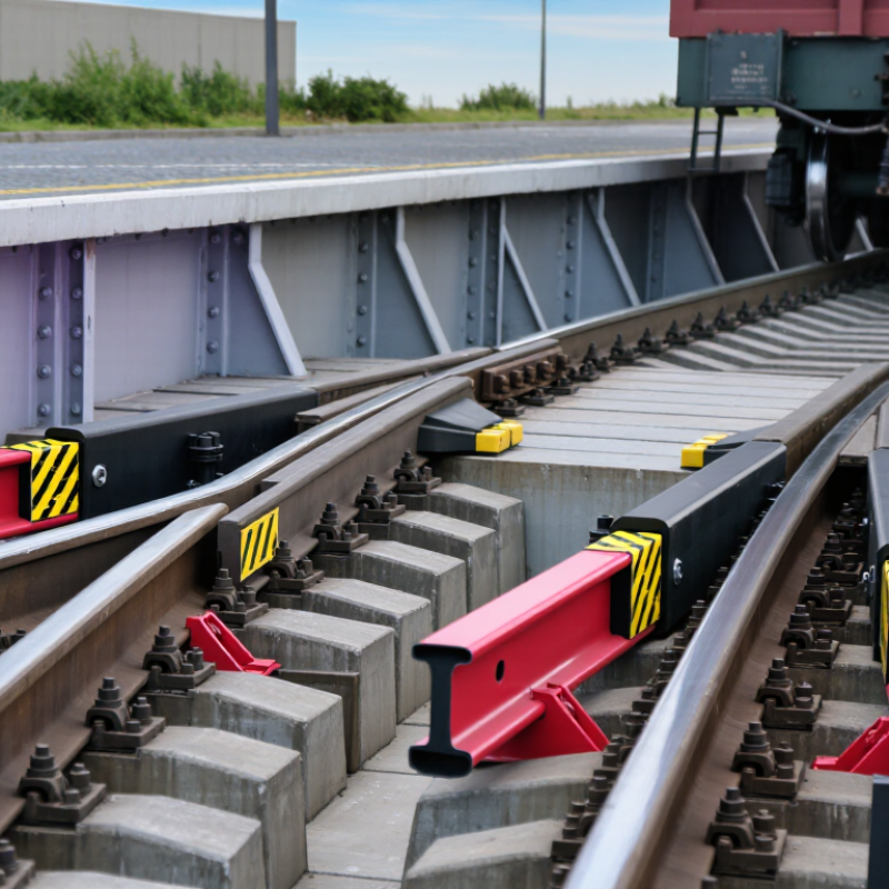
Choose the BF buffer stopper by starting with its actual duty: vehicle type, operating loads, and available mounting space. EN 15551:2022 sets requirements for railway vehicle buffers and their interfaces. A 105 mm stroke is common in buffer specifications, but it is not universal. Check the required buffer category, stroke, energy absorption, face dimensions, and fixing arrangement against the vehicle documentation. A matching outline alone is not enough. A neat drawing can still hide a load mismatch.
Tips: Measure the installed interface, including bolt spacing and buffer-face position. Compare these dimensions with the EN 15551 drawing and the supplier’s test documentation. Record the required stroke and energy class before ordering. If the vehicle specification is unclear, pause and ask a qualified rail engineer to verify compatibility.
Treat the interface as a working connection, not just a fit. During inspection, look for cracked welds, loose fasteners, uneven contact marks, or a buffer that does not return smoothly. These signs may point to misalignment or wear, though they do not prove the cause. Keep the inspection record beside the part identification and installation details.
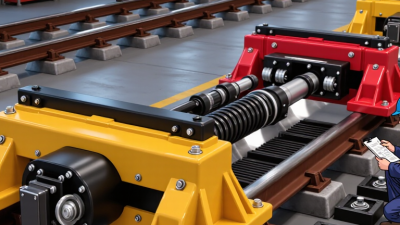
Match Rated Impact Energy (kJ), Approach Speed (km/h), and Stroke (mm)
A suitable buffer stopper BF must absorb the impact energy expected at the end of travel. Check the equipment’s rated energy in kJ, not just its moving mass. Energy rises sharply with speed, so even a small increase in approach speed can change the required capacity. Use the maximum credible operating speed, including loaded movement, rather than an optimistic average.
Compare that demand with the stopper’s rated impact energy and available stroke in millimeters. Stroke is the distance over which the unit absorbs motion; too little can cause a hard stop and high reaction forces. Confirm the approach speed in km/h, impact direction, and mounting stiffness against the product data. Real installations vary. Misalignment, temperature, and repeated impacts may affect performance, so allow a suitable margin and verify assumptions with a qualified engineer. A calculation helps, but it is not the whole site.
Tips: Record load, speed, and stroke together. Check clearance with a tape measure, then inspect mounting bolts after installation. If the speed figure is uncertain, resolve it before selecting a stopper. That step is easy to skip.
How to Choose the Right Buffer Stopper BF
Verify peak impact force against the track and foundation limits, not just the stopper’s energy rating. A useful first check is kinetic energy: a 100-tonne vehicle moving at 10 km/h carries about 386 kJ. If it stops over 0.5 metres, the average resisting force is roughly 772 kN. This is a calculation, not a measured peak; real force can rise sharply with the stopper’s response curve, vehicle coupling, and track conditions. EN 1991-2:2003+A1:2010 addresses railway actions on bridges, but it does not provide one universal buffer-stop impact force. Confirm the applicable infrastructure manager’s criteria and assess rails, sleepers, fastenings, ballast, and foundation together.
Tips: Ask for the force-versus-displacement curve and the test conditions behind it. Compare the stated peak force with allowable loads at the actual installation point. Check both normal operation and credible approach speeds. A tidy energy figure can hide a short, high force spike. The model helps, but it is not the whole story; site stiffness and maintenance condition matter too.
Illustrative peak-force comparison for four operating scenarios. Select a stopper whose verified peak impact force stays within both the track and foundation limits.
Example values only—not product ratings or site limits. Confirm impact force using the stopper manufacturer’s test data and a site-specific assessment of vehicle mass, approach speed, stopping stroke, track capacity, and foundation design.
Start with the track gauge: measure between the rail’s inner faces at the specified point, rather than relying on an old site note. Confirm the measurement against the project drawing and the applicable track standard. Then check buffer-center height from the defined rail-top datum. A few millimeters can affect contact alignment, so record both the measurement and where it was taken. Measure twice.
Check the stopper’s mounting pattern before ordering or drilling. Compare hole spacing, plate dimensions, bolt locations, and the direction the unit faces with the actual support structure. A paper template or full-size drawing can reveal conflicts that a parts list will not. Do not assume existing holes are square or evenly spaced; older installations can be slightly off.
Finally, assess clearance around the buffer and the equipment that approaches it. Allow for the full movement envelope, nearby cables, walkways, and access needed for inspection or replacement. Look from more than one angle. Small gaps matter. I would recheck clearance with the surrounding equipment in its real position, because an empty track can make the fit appear better than it is. If a dimension remains uncertain, pause and verify it with the responsible engineer before installation.
When comparing Buffer Stopper BF options, treat the test certificate as evidence, not a promise of performance in every installation. Check the details. A useful certificate identifies the tested configuration, load conditions, date, and acceptance criteria. Confirm whether the results apply to the exact stopper supplied or to a representative sample. That distinction matters when materials, dimensions, or mounting arrangements differ. A passed sample may not reflect a unit exposed to different loads.
Inspection intervals should match operating conditions, not just a convenient calendar. Record a baseline after installation, then check for cracks, deformation, loose fixings, and changes in clearance. Dust, moisture, repeated impacts, and temperature can all affect wear. Follow the supplier’s inspection guidance, but shorten the interval if checks reveal damage or service conditions are harsher than expected. Keep dated notes and photographs; they make gradual changes easier to spot.
Service-life figures need the same careful reading. Ask what duty cycle, impact energy, and environment support the estimate, and whether it is a tested result or a planning guide. No figure removes the need for inspection. It is easy to overvalue a precise-looking number. I would also record replacements and failures, since local operating history may expose assumptions that the paperwork missed.
| Selection criterion | What to request or record | How to assess the evidence | Practical selection check |
|---|---|---|---|
| Product identification and traceability | Product type, size, configuration, batch or serial number, manufacturing date, and the rated operating conditions. | Confirm that the documents identify the same configuration and batch as the delivered buffer stopper. A generic brochure alone does not establish batch traceability. | Check that identification on the product, delivery records, and supporting documents is consistent. |
| Test and inspection certificates | Request certificates relevant to the component and purchase specification. Where applicable, ask whether an EN 10204 Type 2.2 test report or Type 3.1 inspection certificate is available. | Type 2.2 reports test results based on non-specific inspection. Type 3.1 records results from specific inspection and is validated by the manufacturer’s authorized inspection representative independent of the manufacturing department. Neither certificate type is automatically required for every stopper. | Verify the certificate scope, material or component covered, batch reference, test methods, results, and issuing organization. Do not treat a certificate as proof of suitability for every installation. |
| Design and application data | Rated load or energy absorption data, permitted impact conditions, mounting details, operating temperature range, and any stated environmental limitations. | Use data that applies to the selected size and configuration. Check test conditions and units; do not compare ratings measured under different conditions as if they were equivalent. | Confirm that the intended load, impact frequency, mounting arrangement, and environment fall within the documented limits. |
| Baseline condition at installation | Installation date, product identification, mounting details, initial photographs, and any initial dimensions or condition measurements recommended by the supplier. | A documented baseline makes later changes easier to identify and supports consistent inspection records. | Record the baseline before the stopper enters service, and retain it with the equipment maintenance history. |
| Routine visual inspection | Check for cracking, tearing, permanent deformation, loose or missing fasteners, corrosion, displacement, and visible damage to the mounting structure. | Set the frequency according to the manufacturer’s instructions, impact frequency, consequence of failure, and site risk assessment. For frequently used or safety-critical equipment, a pre-use or shift-based visual check may be an appropriate starting point. | Define who performs the check, what defects trigger escalation, and how findings are recorded. Increase inspection frequency after abnormal impacts or operating changes. |
| Detailed condition inspection | Documented examination of the stopper, fixings, supporting structure, alignment, and measurable wear or deformation. | A monthly review can be used as an example planning interval for some regularly used installations, but it is not a universal requirement. The interval should reflect risk, usage, environment, and inspection findings. | Have a competent person set or approve the interval and revise it if damage, rapid wear, or changing service conditions are observed. |
| Post-event inspection | Inspection after an overload, unusually hard impact, collision, change in alignment, or any event outside normal operating conditions. | Event-based inspection supplements—not replaces—the scheduled inspection plan. Some internal or mounting damage may not be evident from a quick visual check. | Follow the supplier’s assessment guidance and do not return the equipment to service if safety-critical damage is suspected. |
| Service-life evidence | Documented field history or test data stating the application, operating conditions, impact or duty-cycle assumptions, evaluation method, and end-of-life criteria. | Service life depends on load, impact frequency, environment, installation, and maintenance. A stated number of years or cycles is meaningful only when its test or operating conditions are comparable to the intended use. | Prefer condition-based replacement criteria and application-relevant data over an unsupported “typical life” figure. |
| Replacement criteria and records | Written limits for unacceptable cracking, permanent deformation, loose mounting, damage, or wear, plus a record of inspection dates, findings, repairs, and replacement. | Clear criteria help different inspectors make consistent decisions. Follow applicable regulations and the equipment manufacturer’s instructions where they specify stricter requirements. | Keep records with the asset and review them when inspection findings show a change in wear rate or service conditions. |
Note: Inspection examples in this table are planning guidance, not universal prescribed intervals. Confirm the applicable product instructions, site risk assessment, and local regulatory requirements before setting an inspection or replacement schedule.