Leave Your Message

How to Choose Cast-In-Place Anchors?

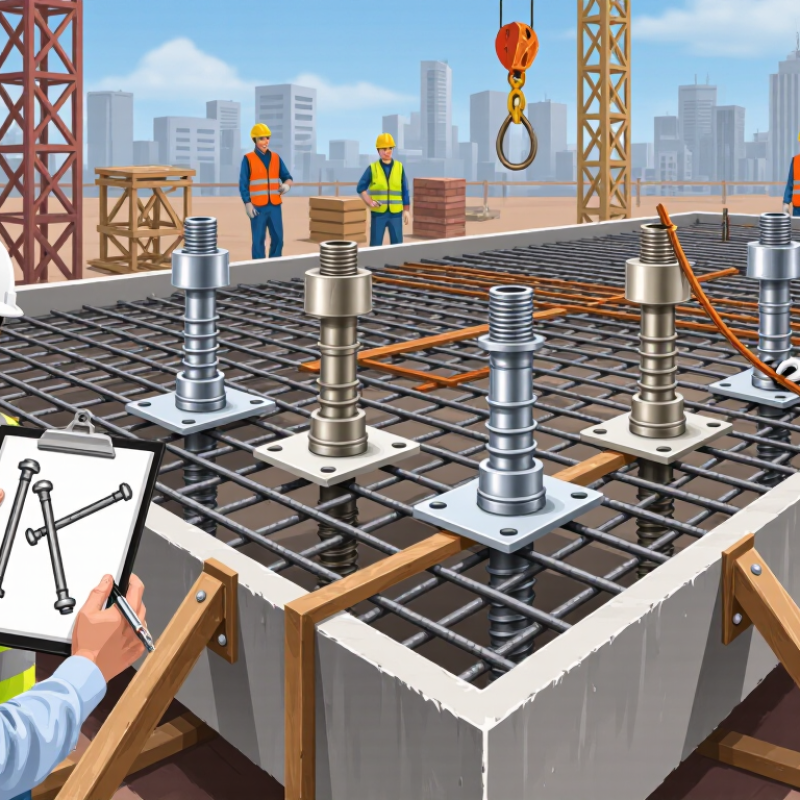
Choosing Cast-In-Place Anchors begins long before concrete reaches the formwork. The decision affects structural capacity, installation accuracy, corrosion resistance, and future maintenance. A suitable anchor must match the applied tension, shear, and moment forces. It must also suit the concrete strength, member thickness, edge distance, and reinforcement layout.

Real projects rarely look perfect. Reinforcing bars may shift, forms may move, and drawings can hide difficult access points. That is why experienced engineers review anchor locations with the construction team before placement. They check embedment depth, plate dimensions, thread protection, and temporary bracing. Small details matter. A few millimeters can change installation results.

This guide explains how to compare anchor types and select a dependable solution for each application. It considers design loads, concrete behavior, installation conditions, inspection procedures, and manufacturer data. Product specifications should be verified against current engineering requirements and applicable standards. Site conditions also deserve attention. Moisture, chemicals, freezing temperatures, and repeated vibration can influence long-term performance.

There is no universal anchor for every structure. A heavy anchor may provide strength but create congestion around reinforcement. A compact option may simplify installation but offer less adjustment tolerance. That trade-off is easy to overlook. Careful calculations, qualified review, and clear installation records reduce uncertainty. The best choice is not merely the strongest product. It is the anchor that performs reliably, fits the design, and can be installed correctly under real job-site conditions.
How to Choose Cast-In-Place Anchors?

Define the Load and Performance Requirements

How to Choose Cast-In-Place Anchors?
Define the Load and Performance Requirements

Anchor selection starts with the load path, not the anchor diameter. List dead, live, wind, seismic, impact, and temporary construction loads. Include tension, shear, interaction, eccentricity, and load reversals. ASCE/SEI 7-22 provides strength-design combinations, including 1.2D + 1.6L for common gravity conditions. Project-specific combinations may differ.

Concrete behavior matters just as much. ACI 318-19 Chapter 17 checks steel strength, concrete breakout, pullout, pryout, and side-face blowout. It also distinguishes cracked from uncracked concrete. Edge distance, spacing, embedment, and reinforcement can control capacity before steel does. ICC-ES AC193 and AC308 qualification criteria evaluate anchor performance through tension, shear, and sustained-load testing. Read the evaluation data carefully. A single published capacity is rarely enough.

Performance requirements should describe the environment and service life. Specify moisture, freeze-thaw exposure, temperature, fatigue, fire conditions, and installation tolerances. For critical work, require traceable batch records, inspection points, and proof testing where appropriate. The U.S. Bureau of Labor Statistics reported 1,075 fatal work injuries in construction during 2023. That figure does not prove anchor failure caused them, but it reinforces a practical lesson: installation control deserves design-level attention. A recurring field-review mistake is treating clean drawings as evidence of reliable installation. They are not. Recheck assumptions against actual concrete strength, reinforcement congestion, and site access. Some designs look efficient on paper, yet leave little tolerance for human error.
Identify the Suitable Cast-In-Place Anchor Type

How to Choose Cast-In-Place Anchors?

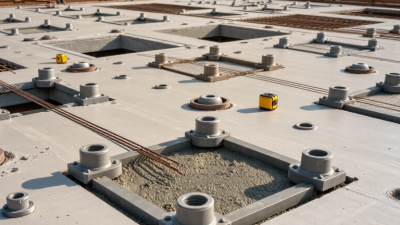
Identifying the suitable cast-in-place anchor type starts with the load path. A headed stud anchor suits direct tension and shear transfer through its welded head. It works well in reinforced concrete connections, base plates, and embedded steel components. Hooked anchors can provide reliable anchorage where space is limited or loads remain moderate. However, their curved shape may complicate reinforcement placement and concrete flow.

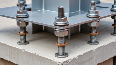
Threaded anchor rods offer flexibility when equipment needs later adjustment or replacement. They may use embedded plates, nuts, or welded accessories to distribute forces. Choose them only after checking thread protection, embedment depth, and installation tolerances. Large loads often require anchor rods with plates rather than simple bent rods. It depends on the concrete condition.

Review cracked and uncracked concrete assumptions, edge distances, spacing, and expected failure modes. Seismic movement, vibration, fire exposure, and corrosion can change the best choice. A stainless or specially protected anchor may suit aggressive environments, but material compatibility still needs verification. I have seen projects focus on tensile capacity while overlooking installation access. That mistake can create expensive field modifications.

Keep it practical. Compare design loads with tested capacity and applicable engineering standards. Confirm reinforcement interference before pouring concrete. A qualified structural engineer should verify the final anchor arrangement, especially for critical connections. The most suitable anchor is not always the strongest one; it is the type that transfers forces safely and can be installed accurately.

How to Choose Cast-In-Place Anchors? - Identify the Suitable Cast-In-Place Anchor Type
Anchor Type Typical Configuration Primary Load Resistance Recommended Applications Installation Considerations Advantages Limitations Relative Load Capacity
Headed Stud Anchor Steel rod with an integral head welded or forged at one end and embedded in fresh concrete. Mechanical bearing from the head provides strong resistance to tension and shear. Structural steel connections, columns, beams, equipment supports, and base plates. Must be accurately positioned before concrete placement. Embedment depth and edge distance must be checked. Reliable load transfer, good resistance to tension, and straightforward design using recognized anchorage principles. Requires access before the concrete hardens; congested reinforcement can make placement difficult. High
Headed Bolt Anchor Threaded bolt with a forged or welded head embedded in concrete, leaving the threaded end exposed. Head bearing transfers tension; the exposed thread provides a bolted connection. Base plates, machinery, structural frames, handrails, and removable assemblies. Protect threads from concrete contamination. Verify projection length, bolt spacing, and template accuracy. Allows nuts and washers to be installed after curing and supports adjustable bolted connections. Misalignment can prevent assembly. Thread damage or inadequate projection may require corrective work. High
J-Bolt Anchor Threaded rod with a curved hook at the embedded end. Anchorage is developed through hook bearing and bond with the surrounding concrete. Light to moderate-duty hold-downs, small equipment, masonry ties, and noncritical fixtures. Hook orientation, embedment, concrete consolidation, and edge distance are important for performance. Simple form, economical installation, and useful where a headed anchor is not required. Load behavior is more sensitive to concrete quality and geometry than a properly headed anchor. Low to Medium
L-Bolt Anchor Threaded rod with a 90-degree bent leg embedded into the concrete. Resistance is provided by bend bearing and bond along the embedded leg. Light-duty equipment, sign supports, small frames, and general-purpose hold-down connections. Ensure the bent leg has adequate embedment and does not conflict with reinforcing steel. Easy to fabricate and suitable for compact anchor layouts. Generally less efficient than headed anchors for high tension loads or heavily loaded structural connections. Low to Medium
Plate Anchor Threaded rod, stud, or anchor assembly connected to an embedded steel plate. Plate bearing distributes force over a larger concrete area and can improve tension resistance. Heavy equipment, large base plates, precast connection hardware, and heavily loaded supports. Plate size, steel thickness, weld quality, cover, reinforcement congestion, and concrete consolidation require review. Provides broad load distribution and can be designed for high tension and shear demands. Heavier and more expensive than simple rod anchors; fabrication and placement require greater control. High
Anchor Rod Assembly One or more threaded rods fixed to a positioning template, often with nuts, washers, sleeves, or a bottom plate. Load transfer depends on the embedded end configuration, such as a plate, head, nut, or welded component. Steel columns, towers, industrial structures, large frames, and precision base-plate connections. Surveying and template control are essential. Check rod projection, spacing, orientation, and grout clearance. Suitable for large anchor groups and precise structural connections with multiple rods. Requires careful coordination between structural, concrete, and steelwork trades. Medium to High
Ferrule Insert Anchor Internally threaded metal insert, commonly paired with a head, plate, or other embedded anchorage component. Threaded engagement transfers load to the embedded anchorage and surrounding concrete. Removable fixtures, temporary supports, precast elements, formwork accessories, and service attachments. Protect internal threads, maintain correct orientation, and confirm the insert is designed for the required load direction. Provides a reusable threaded connection without leaving a long exposed bolt. Capacity depends strongly on the insert geometry, embedment, concrete strength, and load direction. Low to Medium
Cast-In Channel with T-Bolt Steel channel with an opening or slot cast flush into concrete; a compatible T-bolt is installed later. Mechanical engagement between the T-bolt and channel transfers tension and shear. Adjustable façade supports, mechanical services, pipe supports, cable systems, and MEP installations. Channel alignment, concrete consolidation around the channel, bolt engagement, and slot orientation must be controlled. Offers adjustable attachment points and can reduce drilling into structural concrete. Requires compatible channel hardware and may have lower capacity than a dedicated headed anchor for major structural loads. Medium
Selection reminder: Final anchor selection should be based on factored tension and shear loads, concrete strength, embedment depth, edge distance, anchor spacing, reinforcement layout, corrosion exposure, installation tolerances, and the requirements of the applicable design standard. The stated relative capacities are general comparisons, not design values.

Evaluate Materials, Dimensions, and Embedment Depth

How to Choose Cast-In-Place Anchors?

Material selection should match the concrete environment and the expected service life. Carbon steel suits many dry, interior applications. Stainless steel is more appropriate where moisture, salts, or chemical exposure may accelerate corrosion. Check the anchor’s strength, ductility, and coating performance, not only its appearance. Galvanic contact with nearby reinforcement can create problems. Concrete quality matters too. A strong anchor cannot compensate for weak or poorly consolidated concrete.

Dimensions must reflect the actual load path. Review anchor diameter, thread length, head size, plate thickness, and washer area. Larger is not automatically safer. Oversized anchors may interfere with reinforcement or reduce edge distance. Confirm tension, shear, combined loading, and installation tolerances. I have seen drawings that looked precise but ignored a small opening in the formwork. That mistake changed the load arrangement completely.

Embedment depth controls how forces transfer into the concrete. Use the design standard and verified test data for the selected anchor type. Check concrete breakout, pullout, steel failure, pryout, and side-face effects. Deeper embedment may improve capacity, but it can conflict with reinforcement or limited slab thickness. Inspect the projected depth before pouring. Mark the anchor location and secure it against movement. Recheck alignment after placement. Small errors become expensive after concrete hardens. A field adjustment may seem harmless, yet it can reduce edge distance or thread engagement. Conservative judgment is useful, but undocumented assumptions are not.

Check Concrete Conditions and Installation Constraints

How to Choose Cast-In-Place Anchors?

Check Concrete Conditions and Installation Constraints

Choosing cast-in-place anchors starts with the concrete, not the anchor catalog. Confirm the specified strength, concrete age, mix type, and expected curing conditions. Fresh concrete must flow around the anchor without leaving voids. Air pockets near the bearing area can reduce capacity sharply. Inspect drawings for cracks, joints, thin slabs, and nearby openings. These details often change the required embedment and edge distance.

Reinforcement can create an unexpected conflict. Locate bars before fixing anchor assemblies, especially in heavily reinforced beams and foundations. Never move structural reinforcement casually. Ask the design engineer to review any clash. Check the anchor diameter, embedment depth, plate size, and projected load path together. A strong rod is not useful if the surrounding concrete is too thin. Do not guess.

Installation tolerance matters on site. Use a rigid template to hold anchor positions during pouring and vibration. Protect threads from grout, concrete paste, and impact. Confirm the exposed length before the concrete truck arrives. Formwork may limit access, while congested steel may prevent proper vibration. Weather also affects curing and inspection schedules. Record locations, measurements, concrete delivery details, and inspection results. A practical check is to compare the installed pattern with the equipment base before removing forms. Small errors are easier to correct then. Rechecking the layout may feel repetitive, but skipping it can create expensive, avoidable repairs.

Verify Compliance, Testing, and Long-Term Durability

How to Choose Cast-In-Place Anchors?

Compliance should be checked before price. Review the anchor’s design data, installation limits, and concrete assumptions. ACI 318 provides requirements for anchorage strength, edge distance, spacing, and cracked concrete. Qualification testing should follow recognized procedures, such as ACI 355.2 or equivalent evaluation criteria. Ask for test evidence, not only a certificate. Cyclic loading, tension, shear, and installation-error tests reveal weaknesses that static calculations may miss.

Long-term durability needs equal attention. The NACE IMPACT study estimated global corrosion costs at 2.5 trillion dollars annually, or about 3.4% of global GDP. That figure is not specific to anchors, but it shows the financial risk of ignoring corrosion. Check coating type, exposure classification, galvanic compatibility, and expected service life. For marine or deicing-salt environments, stainless or specially protected materials may be necessary. Field experience matters here. A perfect drawing can still fail after poor placement or damaged threads.

Tips: Request independent test reports and batch traceability. Confirm the actual concrete strength before installation. Photograph anchor locations, embedment, and torque records. Do not trust a familiar detail blindly. Some specifications remain vague, and that is where mistakes begin. I would rather pause a pour than accept unclear durability evidence. Review the design again when moisture, temperature, or loading conditions change.