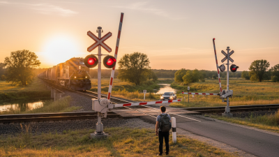
Choosing Rail Crossings is not a catalog exercise. It is a site decision. The right design depends on traffic volume, vehicle mix, track geometry, drainage, maintenance access, and the demands of daily operations. A crossing that works for slow farm vehicles may fail under frequent heavy trucks. Small details matter: a sharp approach angle, standing water, or a surface that shifts beneath a wheel can change performance over time.
Railway engineering expert Dr. Allan Zarembski provides a relevant technical perspective through his work on railway engineering and track maintenance. I cannot verify a direct quotation from him on crossing selection, so I will not invent one. Instead, this guide uses a practical design principle: “Match the crossing to the site, the traffic, and the maintenance plan.” It is a working principle, not a quotation. That distinction matters.
The sections ahead compare crossing materials, load capacity, installation needs, and lifecycle costs. They also consider site inspections and the realities of upkeep. A neat drawing is not enough. Ask how the crossing handles rain, repeated braking, and the occasional delivery vehicle that arrives heavier than expected. Then check whether crews can inspect and repair it safely. Some project choices remain uncertain until site conditions are measured. That deserves a second look. The aim is a defensible selection, grounded in evidence rather than habit.
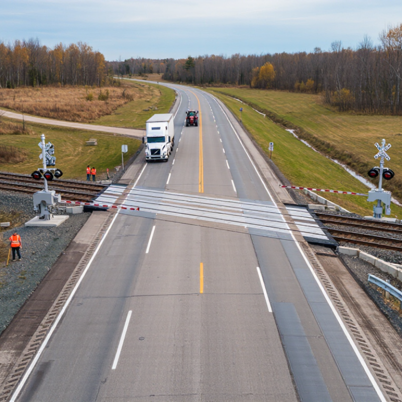
Track gauge is the distance between the inner faces of two rails. At 1,435 mm, standard gauge is a key measurement, not a guarantee that every railway uses the same track. The International Union of Railways’ (UIC) railway statistics and terminology distinguish gauge as a network characteristic; UNESCAP’s Trans-Asian Railway materials also show that corridors can use different gauges. A break of gauge may affect train movement and operations near a crossing.
One detail is easy to overlook.
Gauge alone does not determine crossing type. The U.S. Federal Highway Administration’s Railroad-Highway Grade Crossing Handbook recommends considering train and road traffic, speeds, sightlines, and site geometry. For a project, record the rail gauge, daily train movements, road-vehicle counts, and available stopping distance.
Picture a delivery truck approaching a crossing on a wet, narrow road: vehicle length and sight distance may matter more than the nominal gauge.
Check the measured track against project drawings, too. Measurements can be imperfect.
A 1,435 mm specification helps define the rail system, while traffic and local conditions shape the crossing design.
A 286,000-lb gross rail load describes the loaded car, not the load on one crossing panel. The Association of American Railroads’ Railroad Facts identifies 286,000 lb as a common freight-car capacity benchmark. For a four-axle car, that equals 71,500 lb per axle under a simple static calculation.
A useful starting point, not a complete design rating. Wheel impacts, uneven support, and braking can raise local stresses beyond that neat division.
When comparing panels, ask for a documented load rating tied to freight-car axle loads, installation details, and expected traffic. Check how loads transfer across the panel, rail seat, and supporting surface; a strong panel on a void can still deflect. AREMA’s Manual for Railway Engineering provides professional guidance on track structure and support conditions.
At the site, inspect drainage, settlement, and the approach between pavement and rail. A small lip can concentrate repeated wheel impacts.
On paper, the calculation is tidy. Field conditions are less so. Confirm the supplier’s test basis and whether its rating covers repeated loading, not only a single static load.
Start with the applicable track class and crossing authority, not a catalog dimension. The Federal Railroad Administration’s 2023 National Highway-Rail Crossing Inventory records more than 200,000 public and private U.S. crossings. That scale reflects varied site conditions, not a universal design. Confirm the governing standards, operating speed, rail section, and road-user needs with the track owner.
Measure gauge at several points, including joints and approaches. FRA Track Safety Standards, 49 CFR § 213.53, set gauge limits by track class; 56.5 inches is the standard-gauge reference, not a blanket acceptance tolerance. Check flangeway width and depth against the applicable crossing and track requirements. Make sure wheel flanges pass freely, while avoiding openings that could catch bicycle tires, canes, or small wheels. Small errors matter.
Check clearance against the full vehicle envelope, nearby structures, and expected maintenance access. A tape measure and a clear site sketch help, but they do not replace a qualified track inspection. Record where each measurement was taken and compare it with the approved drawings. A drawing can look tidy while missing a tight spot at the approach. That deserves a second look.
A crossing surface should match both traffic and the work needed to maintain it. The Federal Railroad Administration’s 2023 Highway-Rail Crossing Inventory lists about 130,000 public crossings in the United States. That scale makes site-specific choices important; there is no single surface that suits every road, track, and drainage condition. The Federal Highway Administration’s 2019 Railroad-Highway Grade Crossing Handbook identifies traffic, maintenance access, and site conditions as key design considerations.
Rubber panels are modular, so crews can lift sections for track access and replace damaged pieces. Check joints and fasteners, especially where trucks brake or turn. Concrete handles heavy use well, but settlement or a cracked panel can make repairs disruptive. Asphalt is easy to patch and blends smoothly into the road, yet repeated heavy braking may leave ruts that need attention. Timber can suit irregular approaches and is straightforward to adjust, but inspect for decay, splintering, and loose hardware. Access matters. A detail that looks minor on paper can shape maintenance time. I would compare local repair records before choosing; published guidance cannot predict every site’s wear.
Typical relative maintenance burden by crossing material
Ratings are qualitative comparisons on a 1–5 scale, where 1 indicates lower typical maintenance demand and 5 indicates higher demand. Actual needs depend on traffic, climate, drainage, installation, and inspection practices. Asphalt often needs recurring patching near the rails; timber requires checks for wear, loosening, and deterioration; concrete and rubber systems still need inspections and repairs as components or joints wear.
A rail crossing should be selected for the site it will serve, not just the drawing. Start with drainage. Trace where rainwater travels across the crossing, along the track, and toward the nearest outlet. A low point near a panel edge can trap water, carry fines, and leave a soft spot beneath the surface. Small gaps matter. Check whether drains can be reached for cleaning, and consider snow, sediment, or leaves that may block them.
Installation tolerances deserve equal attention. Compare the crossing system’s requirements with the rail geometry, track spacing, road profile, and available construction space. Confirm how much adjustment is allowed for uneven surfaces and how panels will meet the rails without creating abrupt lips. A few millimeters can affect fit, but the acceptable range must come from the project specifications. Do not assume the field crew can correct every mismatch; that assumption is easy to make and costly to revisit.
Inspection requirements should shape the choice before procurement. Identify which components need routine checks, how they can be accessed, and what signs indicate movement, wear, or drainage failure. Set inspection intervals around traffic, weather, and the crossing’s operating conditions. Record a baseline after installation, including panel alignment and outlet condition. The paperwork can feel minor. It is not. A practical selection makes these checks straightforward, though site conditions may still reveal details the plan missed.
| Crossing surface option | Typical applications | Drainage considerations | Installation tolerances to verify | Inspection focus | Selection notes |
|---|---|---|---|---|---|
| Precast concrete panels | Road crossings with frequent or heavy vehicle traffic where a durable, replaceable panel surface is required. | Confirm that surface runoff has a designed route and cannot pond at the track or undermine the track foundation. Keep drainage paths and outlets clear. | Check panel seating, elevation, joints, track alignment, and required flangeway dimensions against the approved drawings and rail authority criteria. Do not assume a universal tolerance. | Look for rocking or settlement, cracked or spalled concrete, open or damaged joints, debris in flangeways, and changes in track geometry. | Panel weight and lifting access can affect installation and future replacement. Confirm that the supporting foundation and drainage design suit site conditions. |
| Elastomeric or composite panels | Locations where modular components and access to track components for maintenance are useful, subject to traffic and rail-owner approval. | Check how panel edges, joints, and any under-panel spaces interact with the drainage plan. Avoid blocked outlets and persistent water accumulation. | Verify panel fit, seating, edge transitions, joint gaps, and flangeway clearance using the system instructions and project-specific rail requirements. | Inspect for displacement, wear, tears or cracking, loose connections, damaged edges, surface slip hazards, and flangeway obstruction. | Confirm the selected system is approved for the intended vehicle loads, environment, and maintenance approach. Modular construction does not remove the need for precise fit-up. |
| Asphalt crossing surface or approaches | Road approaches and approved crossing configurations where a paved transition is suitable for the traffic and track arrangement. | Set grades and cross slopes so water drains to planned collection or discharge points. Prevent water from being trapped against rails or directed into the track foundation. | Check finished elevations and transitions at the rail interface, pavement profile, and required flangeway dimensions. Use the approved design and applicable road and rail criteria. | Check for rutting, settlement, cracking, loose material, edge breakup, ponding, and pavement encroachment into flangeways. | Coordinate paving limits and construction sequencing with rail operations. Asphalt condition and maintenance needs depend on traffic, support, climate, and drainage. |
| Timber or other engineered modular surfaces | Projects where the rail authority permits the system and the design meets the required load, geometry, and maintenance conditions. | Provide a drainage arrangement that prevents persistent moisture and keeps the track drainage system functional. Check for debris and sediment that could obstruct flow. | Verify component dimensions, fastening, seating, surface level, and clearances to the approved drawings and rail-owner specifications. | Inspect for decay or material damage, loose or missing fasteners, movement, uneven surfaces, and debris or damage affecting flangeways. | Suitability depends on the approved design, exposure, traffic, and maintenance capability. Confirm material durability and replacement requirements for the site. |
| Before selection: Treat the items above as planning considerations, not acceptance limits. Obtain the rail authority’s current requirements and approved crossing details; confirm applicable road, accessibility, and safety requirements; document the drainage design; and agree on installation checks, inspection responsibilities, and inspection intervals with the responsible rail and road authorities. Flangeway dimensions, track tolerances, and inspection intervals are project- and jurisdiction-specific. | |||||